Can you remember what power valve you ended up with and can you remember what vac you had at light cruise?
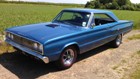
db's 66 Belvedere ***FOR SALE***
Moderator: Moderators

The pv is a 4.5. Vac i think was about 10 pootling around town.JohnS wrote:Sounds good Paul,
Can you remember what power valve you ended up with and can you remember what vac you had at light cruise?
Thanks Mossy
The struts are a fairly easy fix.
The gears I'll leave for now and see if it gets better or worse. At least I know I can free it easily with a big screwy.
The tyre's the only real problem
No-one will believe you...
Started on the front struts tonight.
1st pic is the original bearings which were bolted through the chassis bracket with a rubber washer either side. Utter 5hite!
2nd pic- I realised cos of the angles, my new brackets would need to be different lengths.
I've left a section of the original bracket in place as my guide.
3rd pic- Show Your Workings. At the top is the abandoned Plan 'A'. On the right, the unequal bracket templates.
Pic 4. 1st mock-up. Needs a bit of tweaking but you get the general idea.
- Attachments
-
- Mock up.jpg (167 KiB) Viewed 1209 times
-
- Plan A and plan B.jpg (180.71 KiB) Viewed 1209 times
-
- Chassis and shock angles.JPG (83.21 KiB) Viewed 1209 times
-
- Old bearing.jpg (173.23 KiB) Viewed 1209 times
No-one will believe you...
-
mopar_mark

- Posts: 6738
- Joined: Fri Jul 14, 06 8:01 pm
- Location: Windlesham, Surrey
Can't quite tell from the pics...
In the last picture, with the cardboard tabs, It looks a similar set up to my old front strut setup.
When welding the tabs, I made some equal width spacers, which went either side of the rod end. this allowed me some adjustability.
To be honest, I never had to change, as set up was bang on the money after welding, but I always liked having the ability to have some castor adjustment if needed.
Great work by the way, also love the detailed sketches in your note book too
"I spent a lot of money on booze, birds and fast cars. The rest I just squandered."
See, something I learned in school came in useful!! I always enjoyed Tech Drawing
I have to make accurate drawings otherwise stuff like this just doesn't make sense in my head, I can spot a lot of problems before they become metal!
I'll put spacers in like you suggest. If nothing else, it'll give me more room to weld between the brackets. Ta mate
I have to make accurate drawings otherwise stuff like this just doesn't make sense in my head, I can spot a lot of problems before they become metal!
I'll put spacers in like you suggest. If nothing else, it'll give me more room to weld between the brackets. Ta mate
No-one will believe you...
-
mopar_mark
- Posts: 6738
- Joined: Fri Jul 14, 06 8:01 pm
- Location: Windlesham, Surrey
If you use your digital level, you can establish the set point, mark datum. Then move strut forward 1 degree, mark point. The distance between the 2 marks will give you an idea of spacer size, etcdb wrote:I'll put spacers in like you suggest. If nothing else, it'll give me more room to weld between the brackets. Ta mate
"I spent a lot of money on booze, birds and fast cars. The rest I just squandered."
I sent the budget rod ends back and upgraded to super dooper ultra mega ones.
Bearing Man supplied the taper rollers and Namrick the nuts & bolts.
So, it was out with my trusty angle grinder and I knocked out the 4 brackets.
I found 2 stacks of washers equal to 0.3", assembled the bits and tacked the brackets into place.
I removed the bolt & rod end out of harms way before fully welding.
The sheet I used to protect everything from grinding debris and weld spatter caught fire at least 10 times
I'm chasing my engineer mate to turn proper spacers, loan me a 5/8" x 20tpi tap to lengthen the thread on the shock rod, and to turn the spring retainer plate to fit the taper bearing.
- Attachments
-
- Welded & painted.jpg (193.69 KiB) Viewed 1012 times
-
- Plates tacked with temp spacers.jpg (196.14 KiB) Viewed 1012 times
-
- Unequal plates made.jpg (191.87 KiB) Viewed 1012 times
-
- Brackets and bearings.jpg (201.79 KiB) Viewed 1012 times
No-one will believe you...
My mate Kai helped me get it all back together and set the geometry.
I used my wonderful digi spirit level, and made a very simple but very accurate toe-in gauge.
Camber is 0.5 degrees neg.
Toe-in 2mm.
Castor might be a bit much at 7 degrees, the steering's a bit heavy but very stable in a straight line!
I might pull it back to 5 and see what that's like.
I think the shocks are bottoming out so I'll up the preload a bit for now. New dampers & springs are on the long-term shopping list.
- Attachments
-
- 05 Caster 7 deg.jpg (201.6 KiB) Viewed 960 times
-
- 04 Camber 0.5 neg.jpg (189.14 KiB) Viewed 960 times
-
- 03 Kai adjusting preload.jpg (218.34 KiB) Viewed 960 times
-
- 02 Strut top finished.jpg (194.3 KiB) Viewed 960 times
No-one will believe you...
-
sidewaysjas

- Posts: 177
- Joined: Thu Feb 24, 05 10:10 pm
- Location: Dorset
- Contact:
toe in gauge
Looks good, I made a similar one and it works fine. Okay it doesn't measure down to fractions of a minute but its not F1 stuff.
Jas
Jas
'wouldn't change if I could'