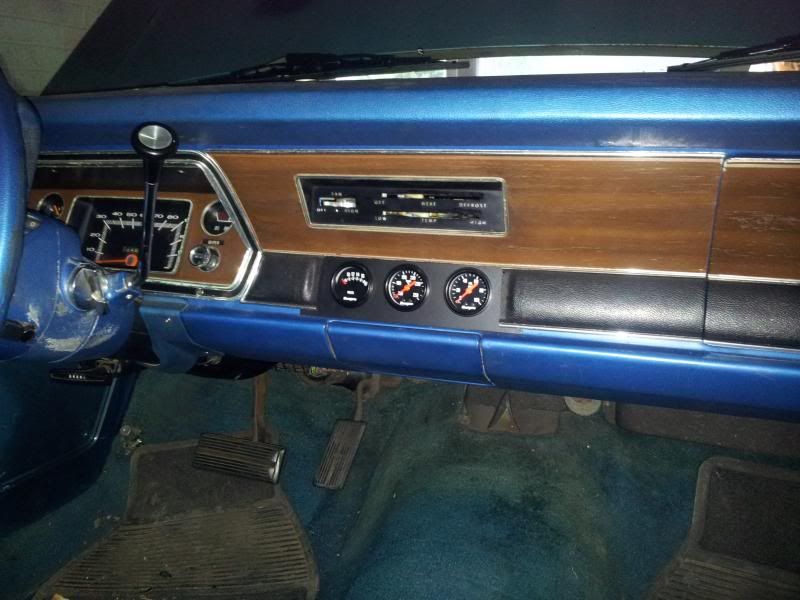
Firstly, and thanks to Daves repeated posting of the MAD conversion thread, I based the bypass on the info contained in it....here it is again
http://www.madelectrical.com/electrical ... uges.shtml
The basic concept of this conversion is detailed in the above link so I wont go into that...its a good, easy read to be honest..
1. Prep....I stripped all the tape off the section of wiring loom I was working on between the starter relay and the bulkhead connector just so I knew for sure I was cutting the correct cables etc, end to end. I also decided to run the new cables through an existing bulkhead grommet rather than through drilled holes in the bulkhead connector. I did this so that I can still take the connector apart without having the solid cable running through it. I also disconnected the battery and removed it from the car
2. I ran a length of 65-0.30 (65 strand 0.30 =metric gauge) http://www.ebay.co.uk/itm/DURITE-AUTOMO ... 43a9faabc1 from the back of the alternator stud, around the bulkhead loom and to the starter relay positive post (the large top one with large nut on it). I put the correct size terminal on the alternator end and just prior to the relay, I fitted a Ford Alternator Fuseable Link http://www.ebay.co.uk/itm/Genuine-Ford- ... 483e609455 with the correct size connector on it. This now means the power from the alternator is going directly to the battery, via the starter relay, instead of from the alternator, through the bulkhead connector to the ammeter, back out the bulkhead connector and into the relay. The old black wire from the alternator is now no longer in use within the engine bay.
3. Next, snip the red wire at terminal 'J' on the bulkhead connector. Disconnect the other end of this wire from the starter relay and bin it. Then push a length of red 65-0.30 wire through the bulkhead grommet, into the drivers footwell and pull about 12" through to work with. Run this wire along the wiring loom to a position near to the starter relay.
4. Find a spot near to the starter relay and screw a fuse holder with a 40 amp flat fuse in it to the fender wall or similar http://www.ebay.co.uk/itm/1-x-MIDI-TYPE ... 4abe0ddc46. Take the end of the 65-0.30 wire you have just fitted and fit a ring connector of the correct size to it and bolt it onto one side of the fuse holder. Make a small lead using the same wire, with another ring connector on it for the other side of the fuse holder and a larger ring connector to fit the positive stud on the starter relay. Then go to the back of the bulkhead connector, cut the other side of the red wire at pin 'P' and solder and heat shrink the new red wire onto the old wire within the dash loom.
5. Now splice a length of black 44-0.30 http://www.ebay.co.uk/itm/5m-LENGTH-BLA ... 2c61be4d7e wire into the new red wire somewhere between the bulkhead grommet and the new fuse holder you have installed. Push this wire through the bulkhead grommet alongside the previously installed red wire. Snip the black wire from both sides of terminal 'P' and join the new black wire into the old black wire in the dash loom. Take the old black wire off the starter relay and bin it. I had to remove the small purple wire from the same connector that the black wire used at the relay and fit a new ring connector to it and refit it to the starter relay positive stud. I think this runs to the horn relay???
6. Finally, remove the wires from the back of the ammeter (Red and Black) and join them together. Bin the old wire that ran from the alternator to terminal 'P' in the bulkhead connector and once tested, tape loom up etc, start car, test alternator output....job done!
I've stuck some pics on and the titles are self explanatory I hope. Would appreciate someone (the more the merrier) just going through this with a fine tooth comb and making sure I haven't missed anything please. Works in my car but want to be sure its correct for everyone.
Thanks for all the help Ive had doing this gents and good luck....if I can do it anyone can!!
Cheers Steve

