Page 2 of 3
Posted: Wed Jan 18, 12 1:06 pm
by db
I thought they should be 3/8" but the A-body one i have and the Competition Engineering one Summit does are also 1/4" so that must be fine.
I'm lnot gonna buy one for less than £150 so i'm gonna look into getting my A-body one modded to fit.
Posted: Sat Jan 21, 12 8:37 pm
by pete walton
Not sure what make mine is,,got it from Kev ....Low fitting alternater from Mancinis ...so is the timing mark set... Now i am no engineer but they do not look that hard to make...And as Pete says,, fit a torque strap ,they flex no matter how powerful the engine is
Posted: Sat Jan 21, 12 8:50 pm
by Pete
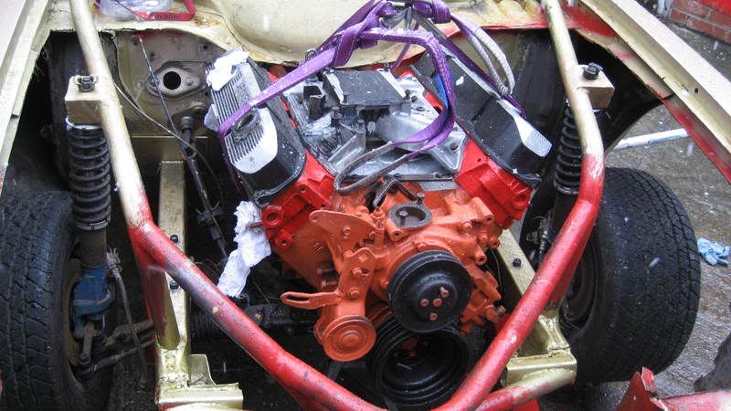
OOOH! One of my heads in the background!!!
If I did not know better I would say tat is one made by Duncan's mate.
It looks the same as the one I had in the Dart............
Posted: Sat Jan 21, 12 9:39 pm
by db
Thanks for the pics Pete. Very similar to the design i came up with!

I'll need to tweak the alternator adjuster & mounts, make a few spacers and source a longer belt from somewhere, but it's looking good.
For now i'm going to extend the A-bod plate i already have.
Where should the torque strap go? Are we talking a rose-jointed bar? or two?
Posted: Sat Jan 21, 12 9:58 pm
by Pete
It's Fore and Aft movement that you need to control.
Take it off the engine mounts and to the chassis - use both engine mount lugs - they have been known to break just one

Posted: Sat Jan 21, 12 10:05 pm
by db
Cool, will do
Posted: Sat Jan 21, 12 10:43 pm
by Jon Connolly
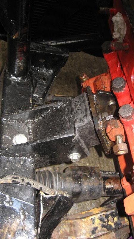
You should have enough room to put a torque strap on your driver side head to the chassis rail or K frame
A tube with 2 rose joints - 1 bolted into the end of your head existing thread and the other onto a piece of angle welded on the chassis rail / k frame
Here`s a pic of mine ( mine was on other side as I didn`t use an alternator )
Hope it helps
Posted: Sun Jan 22, 12 4:37 pm
by Anonymous
If thats standard plywood, I wood step up too Marine ply!
Fink its a tad sronger and waterproof tooooooo?
Have you thought of using aluminum or titanium???
Just trying to be helpful.
BraindeadBacca.
If I remember correctly, most Mopar engines come with lugs cast into the side of the block for mounting porpoises.
Are yours missing?
Only pullin ya leg fella!
Where's me Tablets.
Posted: Sun Jan 22, 12 10:23 pm
by db

A lack of K-member kinda suggested a motorplate would be my best option
Titanium would be nice but it's a bugger to cut. I'll invest in some creosote and hope woodworm don't set in

Posted: Mon Jan 23, 12 12:25 pm
by ANTON
Hi db
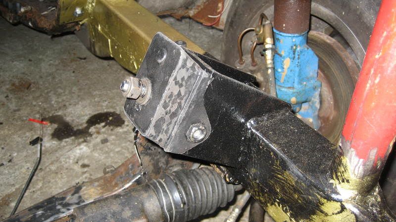
This is the idea i had for you short A-body motor plate.
Steel plate welded to chassis rail on both sides and then bolt motor plate to it with support block welded under plate to take the vertical loading.
Then weld a gusset to the back and use that gusset as your mounting point for your link bar to stop forward and aft movement.
Posted: Mon Jan 23, 12 1:16 pm
by db
Nice idea Anton

Posted: Mon Jan 23, 12 2:37 pm
by Anonymous
On amore serious note!
What effect does the M/P have on the waterpump?
As we are aware the pump blades run fairly close to the timing case.
If you don't use a gasket they actually rub on the case!
If you then fit an M/P then the blades will be up 8-10mm away and I'm pretty sure that will cause cavitation???
I personally would not use a M/P, its pure racecar stuff.
I would always prefer using the standard block mounts and a pair of 2x2inch outriggers coming outta the frame rails, like the early funny cars used to do.
Just my twopennys worth!
I await to be shot down in flames with abuse (as usual) LOL!
Baccaman, whatdoIknow?
Posted: Mon Jan 23, 12 3:19 pm
by autofetish
<a href="
http://photobucket.com" target="_blank"><img src="
http://i73.photobucket.com/albums/i205/ ... G_0296.jpg" border="0" alt="Photobucket"></a>
<a href="
http://photobucket.com" target="_blank"><img src="
http://i73.photobucket.com/albums/i205/ ... G_0295.jpg" border="0" alt="Photobucket"></a>
<a href="
http://photobucket.com" target="_blank"><img src="
http://i73.photobucket.com/albums/i205/ ... G_0178.jpg" border="0" alt="Photobucket"></a>
<a href="
http://photobucket.com" target="_blank"><img src="
http://i73.photobucket.com/albums/i205/ ... G_0304.jpg" border="0" alt="Photobucket"></a>
And easyer to make but db whats to have his brain rattled out his ears.
He could just fit a electric water pump couldnt he

Great work by the way
Posted: Mon Jan 23, 12 3:24 pm
by Dave-R
The way Wil has done it is the way I would do it. Except for the rubber bit. I would solid mount.
Posted: Mon Jan 23, 12 4:43 pm
by Pete
db wrote:Nice idea Anton
I would not do it that way (personal view) as the motor is moving in the centre of the motorplate, not at the edge. The edge of the motorplate is secure.
You need to stop fore and aft movement as near to the crank centre as possible, hence using the motor mounts (or as I did the Trans Cross member to give more header space.)