ignition module question

Moderator: Moderators

Post Reply
User avatar
octanejunkie
Posts: 399
Joined: Thu Dec 04, 14 3:03 pm
Location: Somerset

ignition module question

Post by octanejunkie »

Amongst other things in the order from Rock Auto, i'd ordered a new ignition module for the Charger.
The one that was fitted doesn't look old, but i though i'd just replace everything, then i know its done.
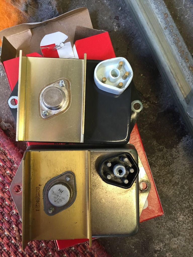
Anyway, the one that turned up had one less pin in it. 4 as opposed to 5.
I did a little bit of digging, and it seems this is a later version with some extra regulating properties..? Does that sound right?
Looks like the wires go to the ballast resistor.

Can someone shed some light on it for me please...
Image
"If its a job no man can survive, he's the man for the job"
User avatar
octanejunkie
Posts: 399
Joined: Thu Dec 04, 14 3:03 pm
Location: Somerset

Post by octanejunkie »

"bump"..

Nobody know??
"If its a job no man can survive, he's the man for the job"
User avatar
Dave999
Posts: 9563
Joined: Thu Feb 24, 05 10:31 am
Location: Twickenham,London, England

Post by Dave999 »

the 5th pin in a 5 pin box was for the second circuit from a dual ballast resistor

with your dual ballast resistor

the 5 ohm section went to pin3
and the 1.2 ohm section went to pin 2


on a 4 pin box the 1.2 ohm section still goes to pin 2 (via the coil)

but the box doesn't need the feed via pin 3 top operate

so if you plug a 4 pin box into a 5 pin car the 5 ohm section of your dual ballast becomes obsolete

just leave all the wiring as it is and it all looks standard

no.3 just doesn't exist so isn't connected


all designed to

1) Cater for voltage drop when the starter is using all the battery power.
then
2) successfully run an 8 volt coil in a 12 volt car when the battery power isn't being nicked by the starter motor and the alternator is cranking out 14.5 volts into the system.

your 8 volt coil has very low primary resistance, so they put a 1.2 ohm ballast resistor in circuit with it to make it look like a 1960s no ballast resistor coil as found on most 4 cylinder cars of the era ( they usually had 3 ohms resistance built in)

it is designed to limit the current that can flow through to coil to approx. 3 amps

the 5 ohm side was regulating a lower supply voltage to a part of the circuit in for the older ECU

new 4 pin ECU has that regulation in built

dave
Attachments
hei_102 (Small).jpg
hei_102 (Small).jpg (52.06 KiB) Viewed 414 times
The Greater Knapweed near the Mugwort by the Buckthorn tree is dying
User avatar
octanejunkie
Posts: 399
Joined: Thu Dec 04, 14 3:03 pm
Location: Somerset

Post by octanejunkie »

Fantastic. Thanks for the heads up. :thumbright:
"If its a job no man can survive, he's the man for the job"
Post Reply