
Been having a few starting problems with the Satellite recently. Pete W kindly came over a few weeks back. With his magic touch and a spare 'chrome box' it started ok. Next plan was to set up kickdown which was fouling on the exhaust, which seems ok now (at least the linkage moves freely & springs back as i think it should), then go for a test drive. But guess what, it wouldn't start again.
This seems odd as since fitting the Orange box last October it's been fine. this did replace the FBO equivalent that lasted a few weeks. We've got one of those new fangled 'Rev'n'Ators' to fit but don't want to fry it.
So i've been trying to check that the Electronic Ignition conversion is connected correctly, changing a few components and generally going blindly round in circles as i'm no sparky.
Most circuits i've seen shows the 4 wires from the ECU connected as i've shown below (which is how it's connected) however there was an article in Mopar Muscle Magazine that said to connect the blue / yellow wire to the other side of the ballast resistor, with the brown wire.
So the other night I swapped the wire on the Ballast resistor but that didn’t help. Just turning over without firing.
So I refitted the Chrome box in place of Pete’s old blue one, and when I turned the key it actually ‘coughed’ while cranking.
But after that I couldn’t get it to fire or even cough again.
I haven't got a meter so can't check actual voltage or continuity, but with a test lamp between the brown wire on the Ballast and earth, the bulb does go bright when turning the key over to 'start' so should be 12v not 9v.
So other things to check?
a. Need to try to check continuity between BR & ECU as the blue / yellow ire has been extended. Also the 5 pin cap is a bugger to fit so I’m not convinced it’s connecting right.
b. ECU itself- is something knackering them?
c. Too much resistance in BR? will check today.
d. Still unsure whether ECU is connected to the correct side of the BR
e. Checked there was a spark off HT lead from coil but unsure how strong it was. So I’ll try to see if there’s a spark at no 1 plug.
f. Reluctor gap, need brass feeler gauge though (non-magnetic).
g. Seems to be a fair bit of play in the top plate in the dizzy so maybe swap back in the old MP one?
Been using the power pack for starting so should be full voltage.
Are there any wiring faults or is it likely dodgy earths or something simple? i have got earths from ECU body, bulkhead to engine, batt to engine & body and the voltage reg is screwed in with a crinkle washer.
Any comments / help greatfully received.
Stu.
Non-Starter - now a starter and appears to be a runner!
Moderator: Moderators
Non-Starter - now a starter and appears to be a runner!
- Attachments
-
- IGN WIRING.jpg (210.58 KiB) Viewed 1322 times
-
- P1110844.JPG (227.62 KiB) Viewed 1322 times

well that diagram shows 12 volts to the coil in the start position
and 9 volts to the coil in run
the blue/yellow is 12 volts power to the box all the time.
all good
you need to find out which of your blue wires goes to the coil.
with them the wrong way round at the ballast when you try to start
you will be sending 9 volts to the coil with a massive load on the battery reducing it further to possibly 6 volts
and in run you will be powering your Box with only 9 volts
which is not enough to push the 2 amps it needs to do its thang
hence car won't run
its a 9 volt coil
when in start you feed battery voltage direct to the coil which should be 12 volts but probably isn't due to the massive impact the starter motor has on the whole system
its something like 10 or 11
If boxes are being killed
do you have an electronic regulator
if you don't the mechanical regulator can cause spikes and can allow a back emf to come out of the coils of the alternator and zap stuff
however unlikley to happen beacsue you tend not to stall when the alternator is active excited and on.
Dave
The Greater Knapweed near the Mugwort by the Buckthorn tree is dying
-
Dave-R

- Posts: 24752
- Joined: Sun Apr 18, 04 11:23 pm
- Location: Dave Robson lives in Geordieland
- Contact:
The ignition switch itself can often cause this problem. But you really need a meter.
1/Remove the wiring connector from the orange box amplifier.
2/Turn the ignition switch ON.
You should have battery voltage (within 1 volt) between earth and pin 1 (blue/yellow wire). Also pin 2 (black/yellow).
3/Turn the ignition OFF.
Pins 4 & 5 connect to the pick-up coil in the distributor. Connect an Ohm meter accross these two pins. The resistance should be within 150-900 ohms (400-600 prefered). If is isn't detatch the dual connector at the distributor and check there. If the coil is still not within spec replace it.
Connect one lead of your ohm meter to earth and the other to either coil pick-up connector. If you get any reading at all replace the pick-up coil.
Dave (999), the V/Reg is fairly new from US Automotive, so i presume it's electronic as opposed to old fashioned mechanical (?), and the coil is an MSD blaster which i thought was 12v.
Re the blue wires, from the photo the 2 blue wires on the V/Reg are part of the new loom and share a plastic female spade. The blue & white one goes off towards the bulkhead connector, and the solid blue one goes in the other direction (presumably to the Ball Res).
On the Ball Res, the blue & brown wires that share a plastic female spade are also part of the new loom. When i get a meter i'll check this blue goes to the coil. On the left hand end, the darker blue has the black plastic spade from the new loom, and the lighter blue is piggy backed and goes to the ECU (an extension i made admittedly, so i'll check the join).
I just checked the resistance of the Ball Res, and one meter said 1.8 ohm, and another said 1.3. So i'll re-check tomorrow with another meter. How important is this, it's supposed to be 1.2 ohm right?
Thanks for both replies i'll try to digest them tonight when the kids have gone to bed....

Had the same problem & replaced the starter relay.
This one fits
http://www.ebay.co.uk/itm/STANDARD-sole ... 56529988d8
This one fits
http://www.ebay.co.uk/itm/STANDARD-sole ... 56529988d8


this sounds very like the traumer Morgan had with his Charger … ??
http://www.moparuk.com/forums/viewtopic.php?t=35517
isn’t that a mechanical VReg you have there?? (unless it’s a mechanical pattern box with electronic internals??)
this is an electronic VReg used from 70 onwards …
http://www.moparuk.com/forums/viewtopic.php?t=35517
isn’t that a mechanical VReg you have there?? (unless it’s a mechanical pattern box with electronic internals??)
this is an electronic VReg used from 70 onwards …
- Attachments
-
- VReg70-.jpg (40.46 KiB) Viewed 1244 times
Si
1970 Charger 500
383 | 4bbl | 727 column | PAS | PAB | buckets/buddy - check out my photos HERE
If you don't want another same old brand-new car ... you could be DODGE MATERIAL
1970 Dodge Charger Registry - https://www.1970chargerregistry.com/
1970 Charger 500
383 | 4bbl | 727 column | PAS | PAB | buckets/buddy - check out my photos HERE
If you don't want another same old brand-new car ... you could be DODGE MATERIAL
1970 Dodge Charger Registry - https://www.1970chargerregistry.com/

Exactly what I was thinking.Charger wrote:this sounds very like the traumer Morgan had with his Charger … ??
Aw man, I feel your pain - been here more than once. Sounds like you have nailed all the obvious things (I too ran extra earths etc). But it is maddening when you cant get anything meaningful to conclude.
I finally laid blame at the door of voltage regulators. Since I got the 'correct' one (FBO, for electronic not mechanical) it seems to behave. Took me about 5 ECUs and 3 voltage regs to get there though.
I have a spare electronic voltage reg and ECU (I carry in the car !!!) which you are welcome to borrow if only for elimination ? Let me know, can pop in the post.
"Cum homine de cane debeo congredi." Woof.
Current Charger status - "Working and awesome"
Current Charger status - "Working and awesome"
your coil if it is 12 volt blaster it will be adding in another 1.5 ohms and is not for use with a ballast resistor
if its a 12 volt blaster "2" or "2F" F for ford, it will be adding 0.8 or 0.7 and is designed to run with a ballast resistor and is therefore much like the orginal coil and will work with the chrylser box
I'll assume its a plain old blaster 12 volt coil in which case you have over 3 ohms in series with the primary..
i.e when you run at 9 volts the coil will see 6 volts only
and when you are in start mode at 12 volts the coil sees about 9
12 volt coils have the ballast resistance In built its usually 1.2 to 1.6 ohms
designed to limit current to the 3 amps that a set of points or the transistor in a chrylser box can switch without melting.
so have you got a ballast resistor coil or a true 12 volter designed for no ballast.
part number should tell us
PS if that black thing is you voltage regulator it looks like a mechancial to me.. nout wrong with them but not good for electronic igntions due to the amount of rubbish they put into the power supply, which makes no difference to a bulb or a wiper motor but tends to upset other things
Dave
The Greater Knapweed near the Mugwort by the Buckthorn tree is dying
oooh, got me thinking now. Maybe i've got a mish mash of parts?
the coil is an MSD8222:
http://www.msdignition.com/Products/Coi ... _Coil.aspx
Can't see from the guff whether it needs a Ballast resistor or not? Is it likely to have been knackered?
Though the V/reg is the old style (not 70 on), i was sure it had the newer electonic internals. I'd rather stick to this style if poss, just for appearance but if i did need the new style i'd need the correct 2 pin plug. But doesn't this just regulate voltage to the alternator? didn't think it had an effect during cranking, going by the circuit.
And the Alternator is a new Powermaster 75Amp from Bouchillon. Not sure whether it's '3 wire'? how do you tell?
Hopefully these parts aren't too incompatible...
Charger01 - it's got a new starter relay. it turns over fine but would this stop it firing?
-
Dave-R
- Posts: 24752
- Joined: Sun Apr 18, 04 11:23 pm
- Location: Dave Robson lives in Geordieland
- Contact:
That MSD coil does not need the ballast resistor. Only if you have points in the dizzy (as it says).
You are running the coil at a low voltage as a result and the spark will be weak. But you will not have done it any harm.
3-wire alternators have the one big output lead and two this field wires.
You are running the coil at a low voltage as a result and the spark will be weak. But you will not have done it any harm.
3-wire alternators have the one big output lead and two this field wires.
Last edited by Dave-R on Thu Oct 03, 13 2:09 pm, edited 1 time in total.
-
Dave-R
- Posts: 24752
- Joined: Sun Apr 18, 04 11:23 pm
- Location: Dave Robson lives in Geordieland
- Contact:
Electronic regulators produce a smoother voltage in the cars electrical system than the old mechanical type. Electronic ignition systems prefer a smoother voltage where possible. FBO do an electrical regulator that looks exactly like the old mechanical one.
It could still be the ignition switch causing your problem.
It could still be the ignition switch causing your problem.

Whist Stu has the better recollection of what parts we have and when/where they were bought, I'm 99.9% sure the voltage regulator is the electronic type.
I read this some time ago in Mopar Action and thought we were going to have to buy one of the GM types and modify it to fit in the old style Mopar casing (as shown below), but I think we (Stu) managed to get a new Mopar VR that has elecetronic internals
I read this some time ago in Mopar Action and thought we were going to have to buy one of the GM types and modify it to fit in the old style Mopar casing (as shown below), but I think we (Stu) managed to get a new Mopar VR that has elecetronic internals


Woah do NOT buy one of these ! I burned through 2 and lost 3 (I think) ignition modules to it. Which in fairness the article does say - I just learned the hard way.
The FBO one (looks old, has electronic internals) is what is keeping me going now.
The later 'flat' 2 pin voltage regs are fine too, just need different ends (my spare is this type).
The FBO one (looks old, has electronic internals) is what is keeping me going now.
The later 'flat' 2 pin voltage regs are fine too, just need different ends (my spare is this type).
- Attachments
-
- volt.jpg (73.03 KiB) Viewed 1188 times
"Cum homine de cane debeo congredi." Woof.
Current Charger status - "Working and awesome"
Current Charger status - "Working and awesome"
Dont worry Morgan, we dont have one of those or the intention of buying one. Maybe we do need an FBO VR (they must make something that works ok?????  ) but as I say, I'm pretty sure ours is the electronic version of the stock pre-70 style.
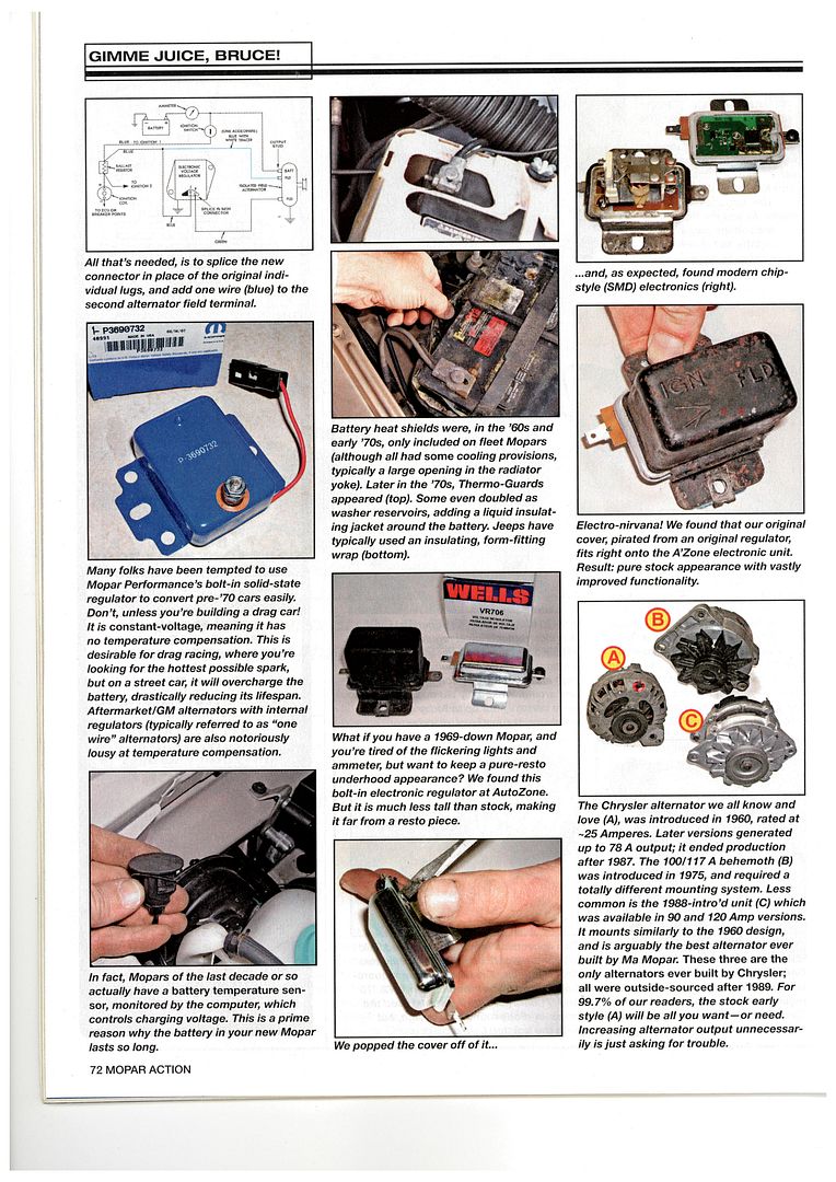
Re Ballast Resistors - I have this article scanned and saved on my work pc, so thought I'd throw it in here in case there's any useful info. At first glance, I see they say right at the end of the 3rd page that you can bypass BR if using elec ign.
Should be an easy test, eh Stu?

Re Ballast Resistors - I have this article scanned and saved on my work pc, so thought I'd throw it in here in case there's any useful info. At first glance, I see they say right at the end of the 3rd page that you can bypass BR if using elec ign.
Should be an easy test, eh Stu?


